TL;DR
Return side guide roller installation involves mounting vertical rollers on the underside of a belt conveyor to prevent lateral belt drift and protect belt edges. The procedure requires lockout/tagout compliance, clean mounting surfaces, proper bracket positioning on the return frame, a roughly 1-inch gap between the roller face and belt edge, and dust covers when the shaft points upward. Guide rollers are stabilizers that complement proper belt tracking, not replacements for fixing root causes of misalignment.
Installing side guide rollers on the return side of a conveyor belt is one of the most effective ways to control mistracking and protect belt edges from damage. But the return run introduces challenges you won’t face on the carry side: tighter access, gravity pulling contaminants into bearings, and low-tension belt behavior that responds differently to correction.
This guide walks through the full return side guide roller installation steps, from planning and safety lockout through post-install verification. Whether you’re a maintenance technician at a quarry, a millwright in a cement plant, or an engineer spec’ing a retrofit, this is the procedure.
If you’re still selecting the right roller for your application, the side guide roller buyer’s guide covers sizing, materials, and selection criteria before you pick up a wrench.
What Is Return Side Guide Roller Installation?
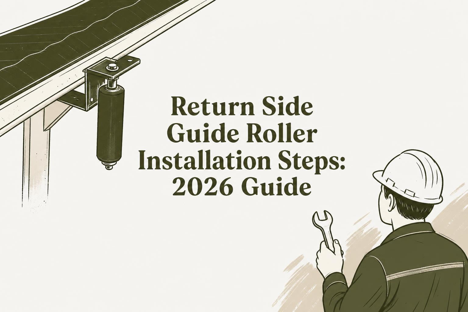
Return side guide roller installation means mounting vertical or near-vertical side guide rollers along the underside (return run) of a belt conveyor. These rollers contact the belt edge when it drifts laterally, pushing it back toward center and preventing the belt from riding off the structure.
The return side matters more than most people realize. Misalignment that starts on the return side often compounds and becomes worse once the belt reaches the carrying section. A belt that tracks off by a few millimeters on the return can wander significantly by the time it hits the head pulley.
Return-side guide rollers are typically placed at strategic locations: just before the tail pulley, behind loading zones, near snub pulleys, at transition areas, and along long conveyors where the belt has room to wander. For a deeper look at placement strategy, see where to position side guide rollers on a conveyor.
Why the Return Side Is Different
Three factors make return side guide roller installation distinct from carry-side work:
Gravity works against you. When guide rollers are mounted on the return side, the shaft often points upward. That means dust, fines, and carryback can fall directly into the bearing core. This is exactly why mechanical dust covers matter for return-side installations, especially in mining and aggregate environments.
Access is harder. Return rollers sit beneath the belt, often in confined spaces between stringers and cross-members. You’re working overhead or at awkward angles. Plan for this.
Low tension changes belt behavior. The return side is the slack side of the belt. It carries less tension than the carry side near the head pulley, which means it responds differently to corrective forces. Guide rollers on the return side need proper clearance to avoid excessive edge contact on a belt that’s already prone to flutter.
An Important Caveat
Multiple authoritative sources, including Kinder Australia and PROK Engineering, stress the same point: side guide rollers are stabilizers, not root-cause fixes. They prevent the belt from wandering off the conveyor while you address the actual tracking problem. If you skip the root-cause work, the belt may eventually ride over the guide roller and sustain further damage.
Understanding how side guide rollers control mistracking helps set realistic expectations for what these components can and cannot do.
Tools and Materials Needed
Gather everything before you start. Working underneath a conveyor is not the time to realize you’re missing a socket.
Tools
- Socket set and combination wrenches (sized to your mounting hardware)
- Torque wrench (capable of 120 to 150 Nm for M20 bolts)
- Measuring tape
- String line or laser alignment tool
- Wire brush or scraper for cleaning mounting surfaces
- Cleaning supplies (degreaser, rags)
- Full PPE: hard hat, safety glasses, gloves, steel-toed boots
Materials
- Side guide rollers (sized to your conveyor specifications). PROGUIDE’s steel side guide roller is built from mild carbon steel with options for heat treatment and contactless sealing, designed to outlast plastic and UHMW alternatives in abrasive service.
- Matching mounting brackets and hardware
- Dust covers (if the shaft will point upward in the installed position)
- Bolts, nuts, and washers per the roller manufacturer’s kit
Before you buy, confirm that the roller’s outer diameter, contact surface length, and bracket bolt hole spacing all match your conveyor frame. A mismatch here creates problems that cascade through the entire installation.
Step-by-Step Return Side Guide Roller Installation Procedure
Step 1: Lockout/Tagout (LOTO)
This is non-negotiable. OSHA’s standard for the Control of Hazardous Energy (29 CFR 1910.147) requires that conveyors be stopped and all power sources locked out and tagged out during maintenance, repair, and servicing. The only exception is when power is necessary for testing, and even then, additional safeguards apply.
The numbers speak for themselves. OSHA estimates that proper lockout/tagout procedures prevent approximately 120 fatalities and 50,000 injuries every year. In mining specifically, “moving machine parts” accounted for more than 3,000 MSHA citations in 2019 alone, costing conveyor owners millions of dollars.
Isolate all energy sources: electrical, hydraulic, pneumatic, and gravitational. Verify zero energy before proceeding.
Step 2: Inspect and Clean
Clean the frame area where brackets will mount. Use a wire brush or scraper to remove carryback, fugitive material, and rust from the stringer or return idler frame. Buildup under the mounting surface means your bracket won’t sit flat, which leads to misalignment from the start.
While you’re down there, inspect the belt edges for existing wear or damage. This tells you how severe the mistracking has been and helps you decide whether additional guide roller positions are needed. Recognizing the signs of a misaligned belt early saves you from more expensive repairs later.
Step 3: Position the Brackets
Place the roller brackets along the conveyor frame at your predetermined intervals. For return-side installations, the bracket typically attaches to the underside of the stringer or directly to the return idler frame.
A matched guide roller bracket simplifies this step because the bolt hole spacing is designed to fit standard conveyor stringers. Hand-tighten the bolts initially. You’ll need room to adjust before final torquing.
Bracket spacing depends on the severity of mistracking and the conveyor’s geometry. PROK Engineering recommends installing “persuaders” (their term for side guides) coming into the tail pulley, just before the loading zone, and after, to help guide the belt back into position downstream of an uneven load. Sometimes more than one guide is needed to distribute the corrective force and prevent belt edge damage.
Step 4: Mount the Roller
Thread the roller shaft through the bracket and secure it with the supplied nuts. PROGUIDE rollers include two nuts per roller for secure fastening.
Make sure the rollers are evenly spaced and parallel to each other on both sides of the belt. Uneven placement creates asymmetric forces that can make tracking worse rather than better.
At this stage, confirm the roller spins freely by hand with minimal effort. If it doesn’t rotate smoothly before the belt is running, it certainly won’t perform properly under load.
Step 5: Set the Gap
This is where precision matters. Aim for approximately a 1-inch gap between the roller face and the belt edge when the belt is centered and running true. This clearance allows the belt to operate without constant contact while still providing correction when drift occurs.
Too tight, and the roller applies constant pressure to the belt edge, accelerating wear. Too loose, and the belt can wander far enough to sustain damage before the roller engages.
Measure on both sides. The gap should be symmetrical.
Step 6: Install Dust Covers
On return-side installations where the roller shaft points upward, gravity allows dust, fines, and moisture to fall directly into the bearing area. This is the most common cause of premature bearing failure in return-side guide rollers.
Mechanical dust covers help keep contaminants out of the inner bearing area. They’re especially critical in mining, aggregate, and cement applications where airborne particulate is constant. If your installation puts the spindle in an upward orientation, don’t skip this step.
Step 7: Torque and Align
Tighten all securing hardware evenly on both sides. For M20 bolts securing idler frames, typical torque specifications fall in the range of 120 to 150 Nm (88 to 110 ft-lb). Always defer to the roller manufacturer’s specifications when available.
Verify that each roller is plumb and square to the belt edge. This is where the string line or laser alignment tool earns its keep. As PROK mechanical engineer Elvin Sey has pointed out, “When you replace a pulley or an idler frame and eyeball it, those slight errors stack up over time and lead to tracking issues.” Even a few millimeters of angular misalignment compounds with every belt revolution.
Use incremental adjustments of 1 to 2 mm at a time. Overcorrection is just as problematic as no correction.
Step 8: Test Under Power
Remove LOTO following your facility’s procedures. Run the belt at slow speed first and observe roller contact and belt behavior carefully.
Watch for:
- Smooth roller rotation without wobbling or vibration
- Belt centering properly when it contacts the guide roller
- No excessive edge pressure or belt deformation at the contact point
- Proper clearance maintained on both sides
Run the belt empty first, then under load. Belt behavior changes with material on the carry side, and the return side responds accordingly due to tension differences.
If the belt consistently contacts one side’s guide roller and not the other, you have a tracking issue that needs separate attention. Guide rollers should be a safety net, not a constant corrective force.
Common Return Side Guide Roller Installation Mistakes
Avoiding these errors will save you callbacks, belt damage, and potential safety incidents.
Skipping lockout/tagout. There is no acceptable shortcut here. The consequences of belt misalignment are expensive, but the consequences of a misaligned belt are nothing compared to the human cost of a lockout violation.
Overtightening rollers against the belt edge. If you set the gap too narrow, the roller applies constant lateral force to the belt edge. Over time, this causes edge fraying, delamination, and accelerated wear. The guide should engage only when the belt drifts, not continuously.
Not addressing the root cause of mistracking. Side guide rollers buy you time and protect the belt, but they cannot fix a skewed idler frame, a misaligned pulley, or uneven loading. A Kinder Australia case study from a South Australian quarry found that guide rollers held the belt in a central position for over two years without major adjustment, but the installation succeeded because the site also addressed underlying alignment issues.
Eyeballing alignment instead of measuring. PROK’s engineers have seen this pattern repeatedly: fitters use slotted holes and eyeball the position during quick replacements. Even small angular errors compound over thousands of belt revolutions.
Forgetting dust covers on upward-pointing shafts. On the return side, this oversight leads directly to bearing contamination and premature failure. It’s a simple add-on that dramatically extends service life.
Not verifying free rotation before starting the belt. A roller that’s binding before the belt runs won’t magically loosen under load. It’ll flat-spot, overheat, or seize.
Post-Installation Checks
The installation isn’t finished when you tighten the last bolt. Follow-up verification catches problems before they become failures.
First 24 hours: Monitor the conveyor closely during initial operation. Watch for roller wobble, unusual noise, or belt edge contact patterns that suggest misalignment. Re-check bolt torque after 24 hours of operation, as vibration and thermal cycling can loosen hardware.
First week: Inspect belt edges for any new wear patterns. If you see fresh scuffing or fraying at a guide roller location, the gap is too tight or the roller isn’t square to the belt.
Ongoing: Real-world mining data shows that belt life increases 25 to 40% when alignment is regularly monitored and corrected. A properly tracking belt also reduces rolling resistance by 3 to 8%, lowering energy consumption. Periodic checks of guide roller condition, bearing smoothness, and gap clearance pay for themselves many times over.
Reversing Belt Considerations
If your conveyor runs in both directions, return side guide roller installation steps remain the same with one important addition: the guide rollers must be positioned symmetrically and must not create directional bias. Field experience at Ontario Trap Rock confirmed that PROGUIDE’s steel rollers work effectively on reversing belts, a scenario where direction-sensitive training idlers often fail.
On reversing conveyors, both sides of the belt become the “leading edge” at different times, so gap symmetry is even more critical than on unidirectional systems.
Why Steel Guide Rollers Matter on the Return Side
The return side is the dirty side. Carryback, fines, and moisture accumulate on the belt’s underside and transfer to everything it touches. Plastic and UHMW guide rollers wear quickly in this environment. Heat-treated steel construction with contactless sealing resists abrasion and impact far better, extending service intervals and reducing maintenance frequency.
For operations dealing with common conveyor belt problems like edge damage and chronic mistracking, upgrading to steel guide rollers on the return side is one of the highest-impact changes available.
Have questions about sizing, installation, or whether your application needs dust covers? Contact PROGUIDE for guidance specific to your conveyor setup.
Frequently Asked Questions
What gap should I set between the guide roller and the belt edge?
Aim for approximately 1 inch (25 mm) between the roller face and the belt edge when the belt is centered and running true. This provides enough clearance for normal operation while ensuring the roller engages before the belt can drift far enough to cause damage.
Do I need dust covers for return side guide rollers?
Yes, if the roller shaft points upward in the installed position. On the return side, gravity pulls dust, fines, and moisture directly into the bearing area. Mechanical dust covers help prevent contamination and extend bearing life significantly.
How many guide rollers do I need on the return side?
It depends on the severity of mistracking, conveyor length, and the locations of problem areas. At minimum, install guide rollers coming into the tail pulley and just before the loading zone. Longer conveyors or those with persistent tracking issues may need additional rollers at regular intervals. Using more than one helps distribute the corrective force and reduces edge stress.
Can side guide rollers fix belt mistracking permanently?
No. Side guide rollers are stabilizers that prevent the belt from wandering off the conveyor, but they do not eliminate the root cause of mistracking. Skewed idler frames, misaligned pulleys, off-center loading, and belt splice issues all need to be addressed separately. Guide rollers buy you time and protect the belt while you make those corrections.
What torque specification should I use for mounting hardware?
For M20 bolts securing idler frames, typical torque values range from 120 to 150 Nm (88 to 110 ft-lb). Always follow the roller manufacturer’s specifications. Re-torque after the first 24 hours of operation.
Do return side guide rollers work on reversing conveyors?
Yes. The key is maintaining symmetrical gap clearance on both sides of the belt so the rollers don’t introduce directional bias. Steel guide rollers with smooth, non-directional contact surfaces are well-suited for bidirectional operation.
Is OSHA lockout/tagout required for guide roller installation?
Absolutely. OSHA 29 CFR 1910.147 requires that conveyors be de-energized and locked out during any maintenance or installation work. MSHA has similar requirements for mining operations. Skipping LOTO is both illegal and dangerous.
How often should I inspect return side guide rollers after installation?
Check bolt torque and roller condition within 24 hours of installation, inspect belt edges within the first week, and then incorporate guide roller inspection into your regular conveyor maintenance schedule. Monthly visual checks and quarterly detailed inspections are a reasonable baseline for most operations.